Guidelines: State Diagram
Topics
Explanation 
A state diagram describes the dynamic behavior of objects in terms of state transitions. You can use state diagrams to model the dynamic behavior of any kind of object. They are particularly important to designers and to the person that unit tests the modeled object or objects associated with it, through, inheritance hierarchies, for example.
Contents 
In creating a state diagram, consider
- The actions an object performs when it transits between states.
- The actions an object performs when it enters into a state.
- The actions an object performs when it exits from a state.
- The actions an object performs when it resides in a state.
State diagrams (and finite state machines) are often presented as graphs, in which nodes represent states, and arcs represent events that lead to state transitions. Arcs in the graph are usually associated with the name of the event that causes the corresponding state transition.
Example 
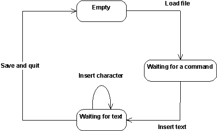
You could view a simple editor, similar to vi, as a finite state machine with the states Empty, Waiting for a command, and Waiting for text. The events could be Load file, Insert text, Insert character, and Save and quit. The corresponding graph is shown below

A graph specifying the state transitions of a primitive editor.
If the editor is in the Empty state, and if the event Load file occurs, the editor will change its state to Waiting for a command when a corresponding Load file action has been performed.
To model an object's dynamic behavior, consider objects as finite state machines. The state the object resides in is a computational state and is defined by the stimuli the object can receive and what operations can be performed as a result. An object that can reside in many computational states is state-controlled. You can think of an object as transiting between one or more such states during its existence. The computational state of an object thus defines the object's potential behavior at a particular moment of its existence.
Use 
The amount of detail you put into a state diagram depends on the behavioral complexity of the object, which, in turn, depends on:
- The number of its different states.
- The number of different events it reacts to.
- The number of different actions it performs that depend on its state.
- Its degree of interaction with its environment (with other objects).
- Its control complexity during state transitions (control complexity is the complexity of conditional, and repetitive, transitions).
Objects you might model using state diagrams are:
- State-controlled objects, such as control objects that control the execution of use cases and boundary objects that manage protocols.
- Any object whose role is clarified by state transitions.
- Complex use cases that are state-controlled.
- Complex actors if, for example, you plan to generate test specifications from them.
- Objects you should not model using state diagrams are:
- Objects with straightforward mapping to their implementation environment.
- Objects that are not state-controlled, such as most entity objects.
Objects that have only one computational state.
![]()